Repair & Service
Hydraulic Cylinder REPAIR UNDERSTANDING Internal Leakage: Diagnosis, Prevention, and Repair
Hydraulic cylinder internal leakage represents one of the most critical yet frequently overlooked failure modes in industrial hydraulic systems. Unlike external leakage – which is immediately visible and prompts urgent action – internal leakage occurs silently within the cylinder, gradually degrading performance until catastrophic failure occurs. This comprehensive guide explores every aspect of hydraulic cylinder internal leakage, from the fundamental physics underlying bypass flow to practical diagnosis and repair strategies.
Internal leakage costs industries billions annually through lost productivity, equipment damage, and emergency repairs. Early detection and prevention can save organisations 40–60% of repair expenses while extending equipment lifespan significantly.Hydraulic cylinders are the muscle behind heavy equipment across mining, construction, manufacturing, agriculture and transport. When they fail, downtime is immediate, expensive and disruptive. This guide explains how hydraulic cylinders fail, how they are professionally repaired, how they are tested, and how to extend their service life using proven engineering best practices.
Table of Contents
- What Is Internal Leakage in Hydraulic Cylinders?
- The Physics Behind Internal Leakage
- Causes and Root Failure Modes
- Symptoms and Warning Signs
- How to Detect Internal Leakage
- Prevention Strategies and Best Practices
- Repair and Replacement Options
- Industry Standards and Compliance
- Case Studies and Real-World Applications
- FAQs About Hydraulic Cylinder Internal Leakage
1. What Is Internal Leakage in Hydraulic Cylinders?
Definition and Scope
Internal leakage in hydraulic cylinders occurs when pressurised hydraulic fluid bypasses the piston seal (or rod seal) and flows from the high-pressure chamber to the low-pressure chamber without performing useful work. This fluid migration creates several problems:
- Loss of Operating Force: The cylinder cannot generate or maintain rated force because pressurised fluid escapes instead of pushing the piston.
- Load Drift: The cylinder cannot hold loads in position; they gradually sink or drift downward when the control valve is in neutral.
- Heat Generation: Internal leakage converts pressure energy into thermal energy through friction, raising fluid temperature 5–25°C above normal operating levels.
- System Inefficiency: The hydraulic pump must work harder to compensate for lost flow, consuming 15–40% more energy for diminished output.
Why Internal Leakage Is Difficult to Detect
Internal leakage differs fundamentally from external leakage in detection difficulty:
External Leakage (Easy to Detect):
- Visible oil puddles and stains
- Dripping from connections or rod seals
- Immediate operator notification
- Clear evidence prompting corrective action
Internal Leakage (Difficult to Detect):
- No visible signs of fluid loss
- Symptoms develop gradually over days or weeks
- Requires specialised testing to confirm
- Often misdiagnosed as valve problems or load issues
- Operators adapt to degraded performance until failure occurs
2. The Physics Behind Internal Leakage: Flow Rate Calculations
Laminar Flow Through Microscopic Clearances
Internal leakage fundamentally represents laminar flow – smooth, orderly fluid movement – through the minute clearance between the piston and cylinder bore. The flow rate through this gap follows the hydraulic clearance flow equation:
Q = (ΔP · π · d · c³) ÷ (12 · ν · ρ · L)
Where:
- Q = volumetric flow rate (m³/second)
- ΔP = pressure differential across the seal (Pascal)
- d = piston diameter (metres)
- c = radial clearance height (metres) — Critical Factor
- ν = kinematic viscosity (m²/second)
- ρ = fluid density (kg/m³)
- L = seal contact length (metres)
The Cubic Relationship: Why Small Clearances Create Massive Leakage
The most important insight from this equation is the cubic relationship (c³) between clearance height and flow rate. This mathematical relationship explains why internal leakage accelerates catastrophically as seals wear:
Example:
- Initial clearance: 0.005 mm (0.000005 m)
- Worn clearance: 0.010 mm (0.000010 m) — only double
- Flow rate increase: 8-fold (because 2³ = 8)
This demonstrates why a seal that maintains marginal effectiveness at 0.005 mm clearance suddenly leaks uncontrollably at 0.010 mm. The wear progression is exponential, not linear.
Practical Example: 25 mm Piston Cylinder
For a typical 25 mm diameter piston with 0.005 mm radial clearance operating at 250 bar pressure:
- Initial leakage: approximately 0.15 ml/minute
- At 0.008 mm clearance: 0.48 ml/minute (3.2× increase)
- At 0.012 mm clearance: 1.62 ml/minute (10.8× increase from original)
This explains why operators notice performance degradation accelerating sharply in the final stages before complete seal failure.
Reynolds Number and Laminar Flow Validation
The laminar flow assumption (Reynolds number
3. Causes and Root Failure Modes of Internal Leakage
Cause #1: Piston Seal Degradation and Wear
Most Common Cause — Accounting for 60–75% of Internal Leakage Cases
Piston seals degrade through cumulative wear over extended operation. Research demonstrates that seal wear is NOT linear but accelerates exponentially as seals approach end-of-life.
Wear Progression Data
Long-term endurance testing of PTFE-based piston seals at 320 bar and full load reveals:
| Service Hours | Travel Distance | Leakage Rate | Status |
|---|---|---|---|
| 0 | 0 km | 0.0011 ml/sec | New seal |
| 500 | 50 km | 0.004–0.005 ml/sec | Moderate increase |
| 1000 | 100 km | 0.009 ml/sec | 8–9× increase |
| 1200+ | 120+ km | > 0.015 ml/sec | Critical failure imminent |
Key Finding: Despite the 8–9 fold increase in leakage by 1000 service hours, seals remained technically functional through 1200 hours — demonstrating that seals possess significant wear margin before catastrophic failure. However, leakage accelerates exponentially in the final operating hours.
Temperature Effects on Seal Degradation
Temperature represents one of the most destructive factors accelerating seal wear:
Normal Operating Range (60–75°C):
- Moderate seal hardening and elasticity reduction
- Gradual leakage increase of approximately 0.001–0.002 ml/sec per 100 hours
- Predictable, manageable performance degradation
Elevated Temperature (82–100°C):
- Accelerated elastomeric material degradation
- Fluid oxidation and additive depletion
- Leakage increase accelerates 2–3× faster than normal temperature operation
- Fluid viscosity decreases, reducing film thickness
Critical Temperature Zones (below -40°C or above 120°C):
- Elastomers undergo glass transition — transition to brittle, glass-like state
- Catastrophic leakage spikes (sometimes 10–100× normal rates)
- Sudden, unpredictable failure without warning
Industry Data: Each 10°C temperature increase above 75°C accelerates seal degradation by approximately 30–40%, meaning operating at 95°C instead of 75°C reduces seal lifespan by 40–50%.
Pressure Effects on Seal Wear Rate
Pressure dramatically accelerates seal wear through three mechanisms:
1. Mechanical Compression Intensification:
Higher pressure forcefully compresses seals into grooves and against cylinder walls, increasing friction exponentially.
2. Extrusion and Creep:
Under high pressure, seal material creeps (slowly deforms) into the clearance gap between piston and bore. PTFE materials exhibit measurable creep starting at 150 bar and significant extrusion above 250 bar. Anti-extrusion rings become essential above 350 bar.
3. Exponential Wear Acceleration:
Experimental evidence shows pressure effects are non-linear:
- 150 bar: baseline wear rate
- 250 bar: 2.5–3× wear acceleration
- 350 bar: 4–5× wear acceleration
- 450 bar: 6–8× wear acceleration
Critical Threshold: Pressures exceeding 320 bar for extended periods cause wear rates increasing 5–8 fold compared to 150 bar operation.
Speed Effects on Internal Leakage
Piston rod speed influences leakage through friction heat generation:
Low Speeds (
- Friction remains controlled; minimal heat generation
- Leakage rates remain stable and predictable
- Thermal effects negligible
Moderate Speeds (0.2–0.8 m/s):
- Friction heat increases progressively
- Localised seal temperature rises 5–15°C above bulk fluid
- Leakage increases 1.5–2× compared to static conditions
High Speeds (0.8–2.0 m/s):
- Friction heat becomes critical factor
- Localised seal temperatures can exceed 30–40°C above bulk fluid
- Leakage increases 2.5–4× compared to static conditions
- Rapid seal degradation at edge zones
Rod Surface Finish Critical at Speed:
Increased piston rod surface roughness (Ra values from 0.2 to 1.6 micrometres) causes proportional leakage increases:
- Rough surface (Ra 1.6): 3–4× higher friction force
- Rough surface (Ra 1.6): 2–3× higher leakage compared to smooth surfaces
- Every 0.5 micrometre increase in Ra approximately doubles friction and leakage
Cause #2: Cylinder Bore Damage
Accounts for 15–25% of Internal Leakage Cases
Cylinder bore damage prevents piston seals from maintaining effective contact with the bore surface, creating bypass paths for pressurised fluid.
Scoring and Surface Degradation
Bore scoring manifests as physical damage patterns created by misaligned or bent piston rods rubbing against the bore during operation:
- Heavy scuff marks and deep gouges in the bore interior
- Localised material removal creating sharp edges
- Characteristic wear patterns often concentrated on one side (indicating misalignment)
- Most severe at cylinder mouth where structural support is weakest
As scoring develops, piston seals lose contact with the damaged surface sections, allowing fluid to bypass the seal in the low-contact zones. This creates a self-amplifying cycle: early scoring reduces seal effectiveness, increasing leakage pressure and erosion rates, which deepens scoring.
Severity Classification:
- Minor scoring (
- Moderate scoring (0.1–0.3 mm): Requires honing plus piston rod replacement
- Severe scoring (> 0.3 mm): May require barrel replacement or boring oversize
Bore Ballooning Deformation
Ballooning occurs when internal cylinder pressure exceeds material yield strength, causing the bore diameter to expand radially. This expansion increases piston-bore clearance, allowing seals to lose hydraulic contact:
Progression Sequence:
- Operating pressure approaches or exceeds design limits
- Cylinder bore walls deflect outward 0.05–0.2 mm
- Radial clearance increases by 0.10–0.40 mm total (both sides)
- Piston seals can no longer maintain full bore contact
- Leakage bypasses the seal through the expanded zones
- Pressure intensification at the bypass increases bore erosion
- Bore diameter expands further — cascade toward catastrophic failure
Critical Indicators:
- Bore diameter increases during pressurisation cycle (detected through precision measurement)
- Pressure-dependent leakage — leakage increases non-linearly with pressure
- Honing cannot restore concentricity or correct leakage
Bore Out-of-Roundness and Ovality
Manufacturing tolerances, thermal effects, and operating pressures can distort the bore into an elliptical (out-of-round) shape. Out-of-roundness of only 5–20 micrometres (0.005–0.020 mm) severely degrades seal performance:
- Seals cannot maintain uniform contact around bore circumference
- High-contact zones experience accelerated wear
- Low-contact zones create fluid bypass channels
- Piston rocks side-to-side during operation
Engineering Finding: Out-of-roundness often more destructive than actual bore wear. A worn bore maintaining round geometry performs better than an unworn bore that has become out-of-round.
Measurement Requirement: Bore out-of-roundness ≤ 0.01 mm (0.0004″) necessary for proper seal function. Bores exceeding 0.025 mm (0.001″) ovality require honing or barrel replacement.
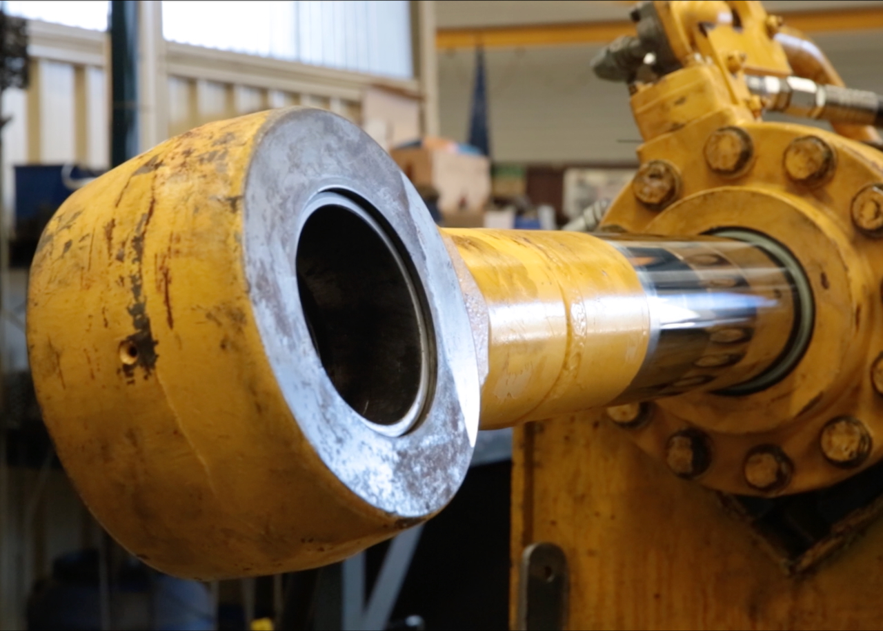
Cause #3: Piston Rod Defects and Misalignment
Accounts for 10–15% of Internal Leakage Cases
Piston rod surface condition and alignment critically affect seal performance.
Chrome Plating Failure and Surface Degradation
Hard chrome plating on piston rods provides:
- Low-friction sliding surface for seals (0.1–0.15 coefficient of friction)
- Corrosion protection against rust and pitting
- Hardened surface preventing seal damage from dirt or contamination
When chrome plating fails through corrosion, mechanical damage, or environmental attack:
- Base steel rod begins corroding rapidly
- Surface roughness increases dramatically (Ra increases from 0.2 to 0.8–1.2 micrometres)
- Corroded surface tears passing seals, accelerating seal wear
- Rust particles contaminate hydraulic fluid
- Rod loses effective sealing surface, sometimes losing 50% effectiveness
Corrosion Sources:
- Salt spray environments (marine, coastal industries)
- Water contamination in hydraulic fluid
- Galvanic corrosion from incompatible metals
- Inadequate protective coatings
Rod Bending and Misalignment Effects
A bent piston rod causes the piston to operate with radial offset from the cylinder axis. Under load, misalignment creates:
- Uneven Seal Wear: One side of the piston experiences high contact pressure; opposite side remains slack.
- Metal-to-Metal Contact: Guide rings contact bore on tight side, creating additional friction and scoring.
- Accelerated Bore Damage: High-contact zone experiences erosion and scoring.
- Seal Rapid Failure: Uneven stress on seals causes rapid degradation — seals may fail within days to weeks of operating with bent rod.
Causes of Rod Bending:
- Operator abuse or impact loading during operation
- Improper handling during installation or maintenance
- Unexpected side loads exceeding design limits
- Fatigue failure from cyclic loading near column buckling limits
- Inadequate mounting support
Detection Method: Use dial gauge to measure rod runout (deviation from true straightness). Maximum acceptable runout: 50–150 micrometres depending on bore size and application.
Cause #4: System-Level Issues Contributing to Internal Leakage
Control Valve Spool Leakage (Indirect Cause)
While technically external to the cylinder, control valve spool leakage directly causes internal leakage symptoms through pressure unbalancing:
Pressure Intensification Mechanism:
- Worn or scored 4-way directional valve spools allow internal leakage between spool lands.
- Leakage oil from high-pressure spool enters the blind end (cap or rod end) of the cylinder under pressure.
- This elevated pressure on the low-pressure side creates pressure imbalance across the piston.
- The differential pressure across piston seal creates net force, pushing the piston and causing drift.
- Piston movement generates pressure intensification at the opposite seal.
Example Calculation:
A 50 mm bore cylinder (π × 25² = 1,963 mm²) with 10 mm diameter rod (π × 5² = 79 mm²) has a differential area of 1,884 mm². At 280 bar system pressure, valve spool leakage creates a drifting force of:
Force = 280 bar × 1,884 mm² = 52.75 kN (approximately 5.4 tons) pushing one direction without operator command.
Pilot-Operated Check Valve Performance Limitations
Pilot-operated check valves (P.O. checks) prevent drift by:
- Blocking reverse flow under normal conditions
- Opening only when piloted from opposite cylinder port
- Providing near-zero leakage through poppet seal design
However, P.O. checks have limitations:
- Pressure Maintenance (Not Relief): They maintain pressure but do NOT relieve excess pressure.
- Thermal Expansion Issues: Prolonged pilot pressure or system thermal expansion can build pressure until exceeding piston seal rupture strength.
- Spool Leakage Bypassing: If the directional valve develops severe spool leakage, pilot pressure cannot reach sufficient value to open check valve, allowing drift.
Contamination-Induced Seal Damage
Contamination particles directly damage piston seals and bore surfaces:
Particle Size Damage Thresholds:
| Particle Size | Behaviour | Effect on Seals |
|---|---|---|
| Pass through seals without damage | Minimal direct damage | |
| 3–10 µm | Lodge in seal grooves and roughness | Reduce seal effectiveness 10–20% |
| 10–25 µm | Trapped between piston and bore | Force seal gap open; create wear paths |
| > 25 µm | Major blockage and damage | Immediate seal and bore damage |
Water Contamination Severity:
Water in hydraulic fluid accelerates seal degradation 3–5× faster than dry fluid:
- Initiates corrosion on steel bore and rod surfaces
- Reduces oil film thickness through lower lubricity
- Causes hydraulic fluid hydrolysis, breaking down additives and seal material
- Creates electrochemical corrosion of ferrous components
- Emulsifies with oil, creating foam that compresses and cavitates
4. Symptoms and Warning Signs of Internal Leakage
Early Stage Symptoms: First Indicators of Trouble
Symptom #1: Cylinder Drift Under Load
What It Means: The cylinder rod slowly moves downward (or moves in the direction of lower resistance) when the control valve is placed in neutral position. This represents the FIRST and most reliable early indicator of internal leakage.
Drift Rate Correlation with Leakage Severity:
| Drift Rate | Leakage Severity | Action Required |
|---|---|---|
| Minimal leakage ( | Monitor; continue operation with caution | |
| 1–5 mm per 5 minutes | Minor leakage (0.05–0.15 ml/sec) | Plan repairs within 1–2 weeks |
| 5–20 mm per 5 minutes | Moderate leakage (0.15–0.50 ml/sec) | Schedule repair within 1 week |
| 20–50 mm per 5 minutes | Severe leakage (0.50–1.5 ml/sec) | Immediate repair required |
| > 50 mm per 5 minutes | Critical leakage (> 1.5 ml/sec) | Remove from service immediately |
Why Drift Occurs:
Internal piston seal leakage causes pressure equalisation between cap and rod ends. Without pressure differential, the cylinder loses its force-holding capability. If the rod has mechanical advantage (smaller rod diameter on one side), the differential pressure at the rod differential area creates a net force pushing the rod, resulting in drift.
Important Distinction — Drift vs. Creep:
- Drift: Slow, continuous rod movement when valve is in neutral.
- Creep: Very slow deformation/settling; typically less than 1 mm per hour.
Symptom #2: Slower Cylinder Extension/Retraction Speed
What It Means: The cylinder operates noticeably slower than baseline performance, even with full pump flow.
Physics Behind Speed Reduction:
Pump flow is divided between:
- Useful work moving the load (cylinder extension/retraction)
- Internal bypass leakage returning to tank
As leakage increases, less flow reaches the piston, slowing operation. Example:
- Pump output: 50 LPM
- Baseline cylinder speed: 0.5 m/sec with 5 LPM internal leakage (10% loss)
- With 15 LPM internal leakage: cylinder speed drops to 0.35 m/sec (30% speed reduction)
Operator Experience:
- Machine cycles take 30–50% longer than baseline
- Multiple successive cycles increase system temperature
- Operators compensate by running pump faster, consuming more energy
Symptom #3: Longer Cycle Times and Reduced Responsiveness
What It Means: System response to control valve shifts is delayed, and overall cycle times increase beyond normal baseline.
Why This Occurs:
- Extended cycles: Internal leakage requires longer pump operation to achieve same load displacement.
- Delayed response: Pump must overcome internal leakage before pressure builds to move load; delay typically 1–3 seconds.
- Pressure fluctuations: System pressure becomes unstable, fluctuating 15–25 bar around target pressure as pump struggles against high leakage.
Operator Observations:
- “The machine feels sluggish.”
- “It takes forever to lift the load.”
- “Response is delayed when I move the control stick.”
Mid-Stage Symptoms: Performance Degradation
Symptom #4: Inability to Maintain Load Position
What It Means: Cylinder cannot hold a static load in position; load gradually descends or moves even though control valve is in neutral and no external force is applied.
Critical Difference from Drift:
- Drift: Rod moves in predetermined direction (usually downward) due to pressure imbalance.
- Load drift: Load slowly descends due to seal leakage allowing pressure equalisation.
Load Descent Rate as Diagnostic Tool:
| Load Descent Rate | Leakage Assessment | Action |
|---|---|---|
| 1–10 mm per hour | Minor leakage | Acceptable for non-critical; monitor |
| 10–50 mm per hour | Significant leakage | Repair needed within 1–2 weeks |
| 50–200 mm per hour | Major leakage | Repair needed within days |
| > 200 mm per hour | Critical | Remove from service immediately |
Safety Implications:
Load holding failure represents a serious safety hazard. Unpredictable load descent can:
- Crush personnel working beneath suspended loads
- Damage equipment or materials
- Create unplanned operational downtime
- Result in worker injury or fatality
Symptom #5: Pressure Gauge Fluctuation
What It Means: System pressure gauge shows erratic readings, fluctuating 15–40 bar around the setpoint rather than maintaining steady pressure.
Why Pressure Fluctuates:
Internal leakage creates an additional flow load on the pump. As the pump compensates by increasing flow, pressure temporarily spikes. Then leakage carries away this extra flow, pressure drops, and the cycle repeats. In severe cases, this creates 0.5–2 Hz oscillation.
Diagnostic Value: Pressure fluctuation becomes more pronounced:
- Under higher loads (pressure differential increases leakage rate)
- At higher fluid temperatures (viscosity decreases, leakage increases)
- During sustained cylinder operation (pump cannot respond fast enough)
Advanced Stage Symptoms: Imminent Failure
Symptom #6: Elevated Hydraulic Fluid Temperature
What It Means: System fluid temperature rises 10–25°C above normal operating levels (which typically range from 65–75°C).
Heat Generation Mechanisms:
Primary Mechanism – Friction Heat:
- Pressurised fluid forced past piston seal at high velocity.
- Friction converts pressure energy to thermal energy.
- Heat generation = Leakage flow rate (LPM) × Pressure drop (bar) ÷ 600.
- Example: 10 LPM leakage at 250 bar = 4.2 kW heat generation.
Secondary Mechanism – Fluid Erosion Heat:
- High-velocity jet through bypass gap creates turbulence.
- Erosion patterns amplify heat generation.
- Localised temperatures at seal can exceed 40–50°C above bulk fluid.
Temperature Effects on Performance:
Temperature increase accelerates seal degradation through a vicious cycle:
- Internal leakage generates heat → Fluid temperature increases.
- Elevated temperature → Oil viscosity decreases.
- Lower viscosity → Internal leakage increases (viscosity in denominator of flow equation).
- Increased leakage → More heat generation.
- Return to step 1: Cycle repeats and accelerates.
Temperature Alarm Thresholds:
- Normal: 65–75°C
- Caution: 75–85°C — Check for internal leakage
- Warning: 85–95°C — Investigate immediately; begin monitoring
- Critical: > 95°C — Take corr